
TYPE C connector pin definition
◆24P USB-TypeC pin definition
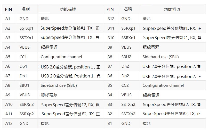
USB 2.0 differential signals will only connect to one side. Because the USB Type-c plug does not have B6 and B7
◆16P USB-TypeC pin definition
The 24-pin, full-featured Type-C is convenient, but the interface is expensive to purchase. Furthermore, the MCUs used in small appliances don't have USB 3.0 support, so USB 2.0 is sufficient for general devices, which is why the 16-pin Type-C was developed.
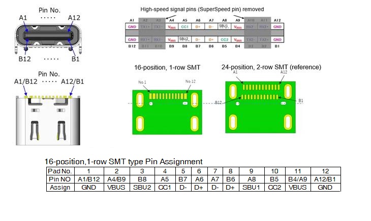
The 16-pin Type-C is based on the 24-pin connector, but it removes the TX1/2 and RX1/2 of USB3.0, and retains the SBU1/2, CC1/2, and D+ and D- of USB2.0. It is identical to the 24-pin connector except for the lack of USB3.0/3.1 high-speed transmission. It also supports PD fast charging, audio devices, HDMI transmission, debug mode, and other functions.
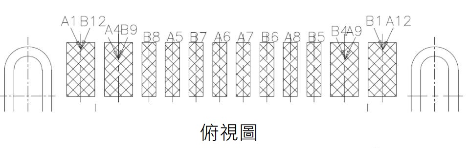
◆12P USB-TypeC pin definition
16-pin is generally the official name given by connector manufacturers, but in daily life, it is usually called 12-pin. This is because the two Vbus and GND output lines at both ends of the Type-C female connector are combined during the interface design, resulting in 16 output lines, but only 12 solder pads are required.
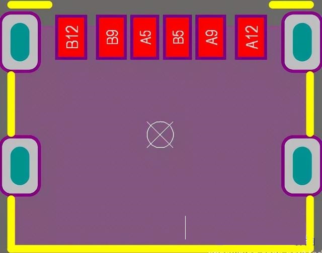
◆6P USB-TypeC pin definition
For many everyday items like toys and electric toothbrushes, which don't require USB communication and only require USB charging, USB 2.0 can be omitted. The 6-pin Type-C connector has officially debuted.
The 6-pin Type-C connector retains only Vbus, GND, CC1, and CC2. Two GND and Vbus pins are symmetrically located on either side of the connector, ensuring reverse insertion protection. The thicker wires also facilitate high-current transmission. CC1 and CC2 are used for PD device identification and carry USB-PD communication to request power from the power supply. USB data transmission remains unaffected while power is being transmitted.
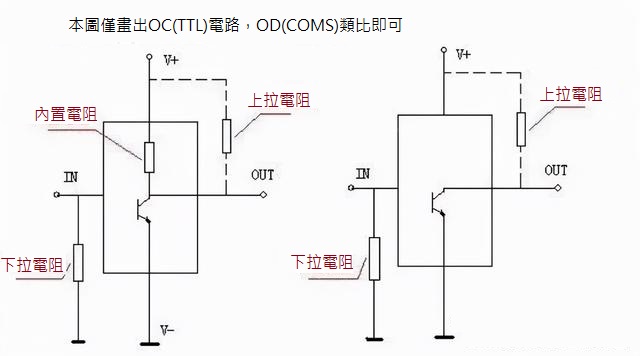
What are pull-up resistors and pull-down resistors?
Resistors limit current in circuits. Pull-up and pull-down resistors are frequently mentioned and used. They are used in large numbers in every system design. Simply put, a pull-up resistor connects the power supply to a device pin and maintains the pin at a high level. A pull-down resistor connects the ground to the device pin and maintains the pin at a low level. A low level is connected to GND within the IC; a high level is connected to a large resistor within the IC. A pull-up clamps an uncertain signal to a high level through a resistor, which also acts as a current limiter. The same principle applies to pull-downs. For circuits with non-open-collector (or open-drain) outputs (such as ordinary gate circuits), their ability to increase current and voltage is limited. The main function of pull-up and pull-down resistors is to provide an output current channel for open-collector output circuits. Pull-up injects current into the device, while pull-down outputs current. The strength of the pull-up or pull-down resistor is simply a difference in the resistance value of the pull-up or pull-down resistor, and there is no strict distinction. When the I/O port node of the IC is at a high level, the impedance between the node and GND is very large, which can be understood as infinite. At this time, it is connected to VCC through a pull-up resistor (such as a 4.7K ohm or 10K ohm resistor), and the voltage divider of the pull-up resistor is almost negligible. When the I/O port node needs to be at a low level, it can be directly connected to GND. At this time, VCC and GND are connected through the pull-up resistor (such as a 4.7K ohm or 10K ohm resistor), and the current passing through is very small and can be ignored.
Brief description of the functions of pull-up resistors and pull-down resistors
1.Increase the voltage level
When a TTL circuit drives a CMOS circuit, if the high level output by the TTL circuit is lower than the lowest high level of the CMOS circuit, a pull-up resistor must be connected to the output end of the TTL to increase the value of the output high level; an OC gate circuit must be added with a pull-up resistor to increase the output high level value.
2. Increase the driving capability of the output pin
Pull-up resistors are also commonly used on some microcontroller pins.
3. N/A pins (unconnected pins) are anti-static and anti-interference
On CMOS chips, to prevent damage from static electricity, unused pins must not be left floating. Pull-up resistors are typically connected to reduce input impedance and provide a discharge path. Furthermore, floating pins are more susceptible to external electromagnetic interference.
4. Resistance matching
Suppress reflected wave interference. Resistor mismatch in long-line transmission can easily cause reflected wave interference. Adding pull-down resistors to match the resistance can effectively suppress reflected wave interference.
5. Preset space state/default potential
Pull-up or pull-down resistors are connected to some CMOS inputs to set a default potential. When these pins are not in use, they are pulled down to a low level or pulled up to a high level. The idle state on buses like I2C is established using these pull-up or pull-down resistors.
6. Improve the noise margin of chip input signals
If the input is in a high-impedance state, or if the high-impedance input is left floating, a pull-up or pull-down resistor is required to prevent it from being affected by random voltage levels and thus affecting circuit operation. Similarly, if the output is in a passive state, a pull-up or pull-down resistor is required, such as if the output is simply the collector of a transistor, to improve the chip's input signal noise tolerance and enhance anti-interference capabilities.